A **GPIO** is a software-controllable peripheral used to configure the device IO ports, also called pins.
GPIOs are grouped in ports and so each GPIO has an identifier.
The identifiers have the following format: `PXY`, where `X` is the GPIO port name and `Y` is the pin number.
## Introduction
GPIO ports' registers are mapped to well defined memory addresses. This means that by accessing those addresses, we directly access the GPIO registers.
Then, we can define a structure that represents the memory layout of the GPIO registers:
```cpp
typedef struct
{
volatile uint32_t MODER;
volatile uint32_t OTYPER;
volatile uint32_t OSPEEDR;
volatile uint32_t PUPDR;
volatile uint32_t IDR;
volatile uint32_t ODR;
volatile uint16_t BSRRL;
volatile uint16_t BSRRH;
volatile uint32_t LCKR;
volatile uint32_t AFR[2];
} GPIO_TypeDef;
```
Remember that strcut members are allocated to consecutive addresses in memory.
In order to access a specific register (address) we need a pointer to a `GPIO_TypeDef` structure.
Assuming we want to control the `GPIOA` port and that it can be found at `0x48000000`:
```cpp
#define GPIOA ((GPIO_TypeDef *) 0x48000000)
```
By simply changing the pointer address we can access to different GPIO ports.
Via _bitwise operations_ we can modify single bits of the GPIO registers:
```cpp
// set 5th bit of ODR to 1
GPIOA->ODR |= (1 << 4);
// set 5th bit of ODR to 0
GPIOA->ODR &= ~(1 << 4);
// if 5th bit is set to 1
if (GPIOA->ODR & (1 << 4))
{
... // do stuff
}
```
So for example if we want to set a pin of the `GPIOA` port to the high state:
```cpp
GPIOA->ODR |= (1 << led_pin);
```
where `led_pin` is the pin number.
## Configuration
> :warning: **WARNING: Before using a GPIO it has to be correctly configured. A lot of times you can experience non-working code or drivers due to not initialized or configured GPIOs.**
Examples of possible configurations for a GPIO are:
- **Output**: the pin voltage level can be set (logic level high or low)
- **Input**: the pin voltage level can be read (logic level high or low)
- **Alternate Function**: set the GPIO to be controlled by some hardware peripheral, such as an SPI, I2C, UART or timer. You should check your microcontroller's datasheet to know which pins have some alternate function.
Other possible modes are: **analog input**, **input pull-up**, **input pull-down**, **open drain**, **alternate open drain**.
The available pin modes and speeds can be found in the
`gpio_impl.h` inside `libs/miosix-kernel/miosix/arch/<your_arch>/common/interfaces-impl`, according to the microcontroller you are using.
If you want to know more about GPIOs, check out the [GPIO Tutorial - Miosix Wiki](https://miosix.org/wiki/index.php?title=GPIO_tutorial) page.
## GPIO Drivers
Lukily for us, Miosix provides all the needed drivers for manipulate the GPIOs and enabling all their possible functionalities and configurations.
#### 1. Template API
To use a pin in your board you can simply do:
```cpp
// define pin PA5 as somePin
typedef miosix::Gpio<GPIOA_BASE, 5> somePin;
// or alternatively
using somePin = miosix::Gpio<GPIOA_BASE, 5>;
```
To read from that pin:
```cpp
somePin::mode(Mode::INPUT);
int value = somePin::value();
```
To set the pin's logical voltage:
```cpp
somePin::mode(Mode::OUTPUT);
somePin::high();
somePin::low();
```
To set the pin's alternate function:
```cpp
somePin::mode(Mode::ALTERNATE);
somePin::alternateFunction(5); // Specify the alternate function number
```
The above method provides *optimal performance*.
#### 2. GpioPin Class
As an alternative you can use the `GpioPin` class.
```cpp
GpioPin somePin(GPIOA_BASE, 5);
somePin.mode(Mode::OUTPUT);
somePin.high();
somePin.mode(Mode::ALTERNATE);
somePin.alternateFunction(5);
```
> :warning: **WARNING: when configuring GPIOs you should disable interrupts to avoid concurrent calls to *mode()* (for example if it is done at runtime). This can be done since pins configuration is a very fast operation, but it should in general be avoided, in order not to compromise real-time capabilities of Miosix. A normal mutex would introduce more overhead in this case.**
> ```cpp
> void someFunction()
> {
> {
> FastInterruptDisableLock dLock; // disable interrupts
> somePin::mode(Mode::OUTPUT);
> } // dLock scope ends: re-enable interrupts
> }
> ```
## Discovery Board Pins
These are some commonly used pins that you'll need when writing software for _Discovery boards_.
#### STM32F429ZI Discovery
| STM32F429ZI | Pin |
|--------------|------|
| Red Led | PG13 |
| Green Led | PG14 |
| User Button | PA0 |
You can find a complete pin usage description [here](https://os.mbed.com/platforms/ST-Discovery-F429ZI/).
#### STM32F407VG Discovery
| STM32F407VG | Pin |
|-------------|------|
| Blue Led | PD15 |
| Red Led | PD14 |
| Orange Led | PD13 |
| Green Led | PD12 |
| User Button | PA0 |
You can find more in the [user manual](http://www.st.com/content/ccc/resource/technical/document/user_manual/70/fe/4a/3f/e7/e1/4f/7d/DM00039084.pdf/files/DM00039084.pdf/jcr:content/translations/en.DM00039084.pdf) for more.
## Miosix Used Pins
These are some pins that are used by default from the kernel when running on _STM32 micros_ (all paths are referred to `/libs/miosix-kernel/miosix`):
- SD memory: `arch/common/drivers/sd_stm32f2_f4.cpp`
| D0 | D1 | D2 | D3 | CLK | CMD |
|-----|-----|------|------|------|-----|
| PC8 | PC9 | PC10 | PC11 | PC12 | PD2 |
- Serial Ports: `arch/common/drivers/serial_stm32.cpp`
| USART | TX | RX | CTS | RTS |
|--------|-----|-----|------|-------|
| 1 | PA9 | PA10 | PA11 | PA12 |
| 2 | PA2 | PA3 | PA0 | PA1 |
| 3 | PB10 | PB11 | PB13 | PB14 |
- Servo: `arch/common/drivers/servo_stm32.cpp`
| SERVO1 | SERVO2 | SERVO3 | SERVO4 |
|---------|---------|----------|----------|
| PB6 | PB7 | PB8 | PB9 |
Extra
---------------
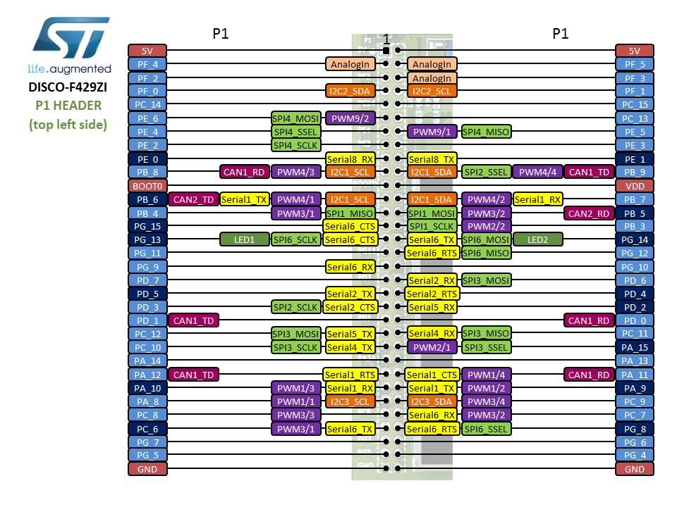
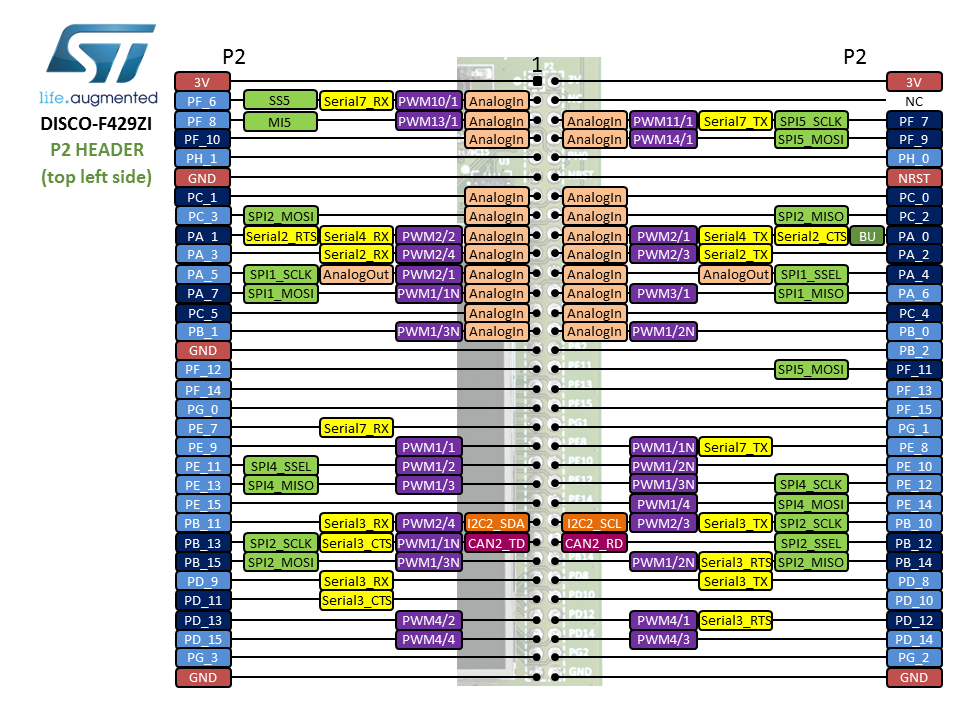
#### STM32F429ZI Discovery Pins